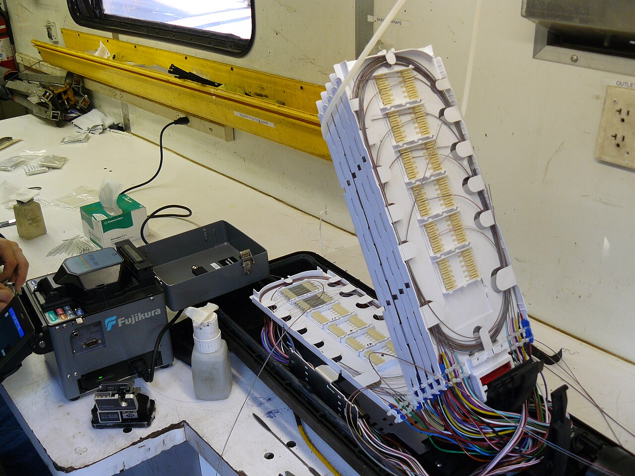
Infrastructure splicing joins the fibre that carries a network from its main spines out to cabinets, poles and buildings. We have hands-on experience splicing this infrastructure on different UK fibre networks, including Openreach, CityFibre and Virgin Media.
Our splicing experience covers different fibre networks, each with its own infrastructure and ways of working.



Logos are trademarks of their respective owners and are shown only to identify the networks we have experience on. Their use does not imply endorsement by, or a current contract with, these companies. CityFibre logo: CityFibre, CC BY-SA 4.0, via Wikimedia Commons, resized.
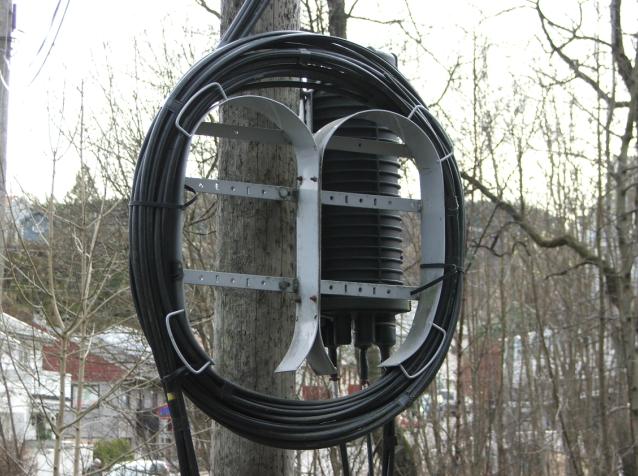
Photo: Haakon hasse, public domain, via Wikimedia Commons.
Splicing and fibre management at street cabinets, the link between the main network and local connections.
Work on pole-mounted closures that carry fibre across overhead routes.
Preparing, splicing and closing joints, with fibres neatly routed and protected.
Splicing inside buildings as well as the infrastructure leading up to the cabinet.
Main spine cables carry large numbers of fibres along the core routes of a network. We splice main spines of up to 864 fibres, using ribbon or single-fibre splicing to suit the cable being installed.
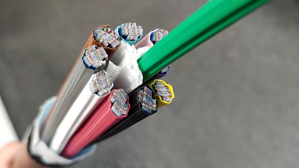
Photo: Infestor, CC BY-SA 4.0, via Wikimedia Commons, resized.
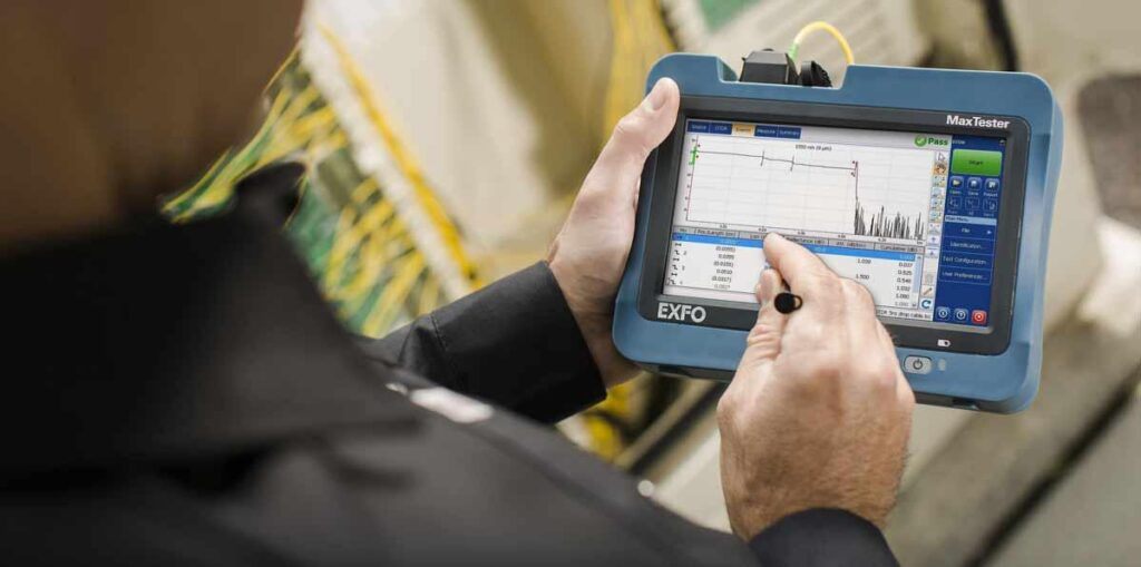
Testing shows that the fibre and its splices perform as they should. An OTDR sends light down the fibre and displays the length, splices and any faults along the route. iOLM testing builds on this by analysing several measurements and presenting the results as a clear map of the link.